Title 5 - SIGNAGE
5.A GENERAL PLAN STANDARDS
5.A.1 Building Mounted - Wall Sign Standards
The following Table(s) shall be used as a
template and shown on either the Master Sign Plan, Alternative Sign Plan, Site
Plan or Regulating Plan, whichever is applicable to demonstrate how the project
is in compliance with Article 8, Signage.
On each Table, Columns 1 and 2 reference the Code section and
requirements, and Column 4 lists the related dimensional requirements. Column 3 is for the Sign ID - alpha-numerical
keys to assist the Applicant and Staff in efficiently identifying where on the
sign elevations the requirements have been met.
Example: The
Applicant should first identify the Sign Area (Numbered 1 in the ID Column) and
then the proposed dimensions and create a callout to label the elevation.
Table 5.A.1 - Wall Signs in U/S Tier (Example illustrated in red)
|
U/S Tier |
||||||
|
ULDC Requirements per Table 8.G.1.A – Wall Sign
Standards |
Sign ID |
Proposed Sign
Dimensions, Separation between signs |
||||
|
|
|
|
Front (East) |
Side |
Side |
Rear |
|
Maximum Sign Area (per linear ft. of the wall to which the sign is attached). |
1.0 sq. ft. along any one side of the building |
W1 |
50 |
|
|
|
|
|
0.5 sq. ft. along any of the remaining sides of the building or 0.25
sq. ft. for walls adjacent to a residential zoning district or use |
|
|
|
|
|
|
Minimum wall sign per tenant space |
24 square feet |
|
|
|
|
|
|
Minimum Horizontal and Vertical Separation between Signs |
3 ft. |
|
|
|
|
|
|
Maximum Projection from Surface of Building |
24 in. |
|
|
|
|
|
|
Minimum Vertical Separation Between Sign and Roof Line |
6 in. |
|
|
|
|
|
|
Minimum Horizontal Separation Between Sign and Roof Line |
6 in. |
|
|
|
|
|
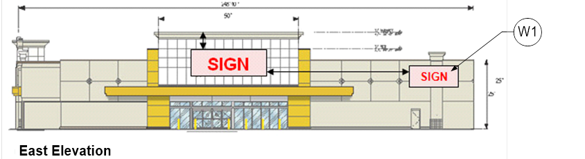
For Wall Signs, an
elevation of the building shall be provided with the
wall sign(s) fully dimensioned with ID Key callouts consistent the Wall Sign
Table.
Figure 5.A.1 - Example of dimensioning wall sign
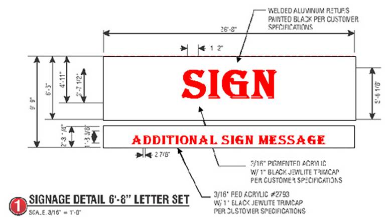
Figure 5.A.2 - Example of wall sign on building elevation
5.A.2 Ground Mounted – Freestanding Signs
The following
Table(s) shall be used as a template and shown on either the Master Sign Plan,
Alternative Sign Plan, Site Plan or Regulating Plan, whichever is applicable to
demonstrate how the project is in compliance with Article 8, Signage. On each Table, Column 1 references the Code
section and requirements, and the remaining Columns list the related required
and proposed dimensional requirements. See
example below:
Table 5.A.2 - Freestanding Signs in U/S Tier (Example)
|
Street Name/Length of
frontage |
Max. No. per Project
Frontage |
Max. Sign Area (1.0 sq.
ft. per lineal ft. of frontage) and Max. Individual Sign Area |
Max. Sign Height (4) |
Min. Setback |
Min. Separation |
||||||
|
|
Allowed |
Proposed |
Allowed |
Proposed |
Allowed |
Proposed |
Allowed |
Proposed |
Allowed |
Proposed |
|
|
Freestanding Signs |
|
||||||||||
|
Okeechobee Blvd 1,200 lin. ft. |
3 |
2 |
600 sq. ft. |
350 sq. ft. |
- |
- |
- |
- |
- |
- |
|
|
Sign A |
- |
- |
- |
200 sq. ft. |
15’ |
12’ |
5’ |
7.5’ |
- |
- |
|
|
Sign B |
- |
- |
- |
150 sq. ft. |
15’ |
8’ |
5’ |
7’ |
- |
- |
|
|
Haverhill Rd 600 lin. ft. |
2 |
1 |
- |
- |
- |
|
- |
- |
- |
- |
|
|
Sign C |
- |
- |
- |
200 sq. ft. |
15’ |
8’ |
- |
- |
- |
- |
|
|
Freestanding Outparcel Identification Signs |
|||||||||||
|
Okeechobee Blvd Sign D |
1 |
1 |
20 sq. ft. |
18 sq. ft. |
6 ft. |
6 ft. |
5 ft. |
5 ft. |
30 ft. |
NA |
|
|
Haverhill Rd Sign E |
1 |
1 |
20 sq. ft. |
18.5 sq. ft. |
6 ft. |
4 ft. |
5 ft. |
6 ft. |
30 ft. |
NA |
|
5.A.3 Sign Plan
For Ground Mounted
signs (freestanding, outparcel identification, entrance, flags, flagpoles,
on-site directional, project identification, off-site directional, etc.), each
proposed sign must be graphically shown on a Sign related Plan (Sign Plan or
Alternative Sign Plan). If more than one sign is proposed for the subject
property, identify each sign with a reference "letter", e.g. Sign A, Sign B, Sign C, etc.